Thursday, April 24, 2014

Electric Motors

An electric motor converts electrical energy into mechanical energy. Most electric motors operate through the interaction between an electric motor's magnetic fields to generate force in the motor. Electric motors can be utilized in numerous applications such as machine tools, industrial fans, pumps, watches, generators, household appliances, power tools as well as many others.
There are many different types of electric motors, this is a graph that shows the different kinds:
Major CategoriesbyType of Motor Commutation

Self-CommutatedExternally Commutated
Mechanical-
Commutator Motors
Electronic-
Commutator (EC)
Motors

Asynchronous
Machines

Synchronous
Machines
ACDCACAC
* Universal motor
(AC commutator
series motoror
AC/DC motor)
* Repulsion motor
Electrically
excited DC motor:
* Separately
excited
* Series
* Shunt
* Compound

PM DC motor
With PM rotor:
* BLDC motor

With
ferromagnetic
rotor:
* SRM
Three-phase motors:
* SCIM
* WRIM

AC motors:
* Capacitor
* Resistance
* Split
* Shaded-pole
Three-phase motors:
* WRSM
* PMSM or
BLAC motor
- IPMSM
- SPMSM
* Hybrid

AC motors:
* Permanent-split
capacitor
* Hysteresis
* Stepper
* SyRM
* SyRM-PM hybrid
Simple electronicsRectifier,
linear transistor(s)
or DC chopper
More elaborate
electronics
Most elaborate
electronics (VFD), when provided
 There are also many different components that are required in order to construct and electric motor:

Rotor: In an electric motor the moving part is the rotor which turns the shaft to deliver the mechanical power. The rotor usually has conductors laid into it which carry currents that interact with the magnetic field of the stator to generate the forces that turn the shaft. This is an example of a rotor and.
Stator:The stationary part is the stator, usually has either windings or permanent magnets. The stator is the stationary part of the motor’s electromagnetic circuit. The stator core is made up of many thin metal sheets, called laminations. Laminations are used to reduce energy loses that would result if a solid core were used.
Windings: Windings are wires that are laid in coils, usually wrapped around a laminated soft iron magnetic core so as to form magnetic poles when energized with current.
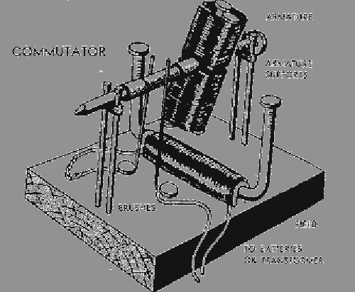
Commutator: commutator is a mechanism used to switch the input of certain AC and DC machines consisting of slip ring segments insulated from each other and from the electric motor's shaft. The motor's armature current is supplied through the stationary brushes in contact with the revolving commutator, which causes required current reversal and applies power to the machine in an optimal manner as the rotor rotates from pole to pole. This diagram shows how a commutator operates:
Source: http://www.seaperch.org/electric_motors

My Motor 2


For the most part, I followed the plan that I laid out for myself in the beginning of the project. One problem I experienced while making the motor was that I could not get my electromagnet to work properly. This was most likely because I overlapped the magnet wire when I wrapped it around the metal. In order to fix this problem I was forced to recreate the electromagnet again. Another problem I was faced with when making the motor was that I could not properly create a proper connection between the commutator and the armature. I am unsure as to why this connection was not formed correctly the first attempt but after re-taping the magnet wire from the armature to the copper plates several times I was able to form a proper connection. The brushes also gave me difficulty because the way I had them situated caused the turning commutator to stop turning. After shaping my L brackets a little differently so that the brushes could come in contact with the commutator while being perfectly vertical, I was able form a successful connection. Although the actual construction of this project did not take an extraordinary amount of time, the tweaking and adjusting of many components took a great deal of time because I was often unsure as to what was wrong with certain connections. However after all of that time, it was a truly amazing feeling to see that I had the capability to make something that worked properly.

Wednesday, April 23, 2014

My Motor 1

In the beginning stages of the motor project, I planned out how I would construct my motor. My original design would be constructed with 24 gauge magnet wire for the armature and electromagnet base instead of using lamp wire for the electro magnet. I did this because I felt that it would be easier and simpler to construct the electromagnet base with magnet wire than single strand lamp wire. In addition, I planned to create the brushes by attaching lamp wire to the outside of a L shaped steel bracket on each side of the armature. One of these L brackets would be connected to the electromagnet base and the other one would be connected by pliers to the battery. The brushes I made would then connect to two copper rectangles that would be shaped around a cork placed on the rod carrying the armature to form the commutator. Also, the two copper rectangles would be connected to the armature in order to transfer the electrical current to it. Lastly, the second plier connected to the battery would be connected to the electromagnet to complete the circuit. My motor was planned to be built to somewhat resemble this model: